BLDC Motor Driver Controller
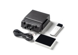
The three-phase BLDC motor driver board is a drive control board based on a 6-step square wave and a Hall sensor to detect the motor position. Including main control board, display board and speed control board. The speed control board outputs the speed control signal to the main control board to implement functions such as starting, braking and speed control. The display board can adjust the maximum running speed, running direction, running mode and display the current speed and other functions. The main control board is the core of the whole system, which has the functions of driving brushless DC motor and protection. It provides a highly reliable control solution for motor drive applications of industrial sewing machines.

| Product Series | LSMF0300WA |
| Input Voltage | 200-264VAC 50/60Hz |
| Driveable Motor Power | 300W |
Features
- Compared with clutch motors of the same power, it saves 60% of electricity. It is highly efficient and energy-saving.
- The brushless motor is driven by the numerical control speed control system, the product can directly drive the sewing equipment, the speed control performance is good, convenient, and sensitive, and the performance is stable, safe, and reliable.
- Maintenance-free, long life, with no carbon brush design, no need to replace any internal parts for long-term use.
- Low noise, less heat. Less interference to other external electronic equipment during operation.
- The adjustable range of motor speed is between 1600RPM and 4200RPM, and the adjustment is cyclically adjusted at intervals of 200 revolutions.
- The structure is simple, the volume is small, and the weight is light, which is half of the weight of the clutch motor with the same power.
Display Board
The display panel includes speed setting keys, working mode keys, motor steering keys, and a double-digit digital tube.
Speed setting button: used to change the maximum speed of the motor. The maximum speed of the motor can be adjusted between 1600RPM and 4200RPM. Each time you press this key, the speed will increase by 200 RPM. When the speed reaches 4200PM, press this key and the speed will return to 1600RPM. When setting, the digital tube will display the first two digits of the motor speed. For example, 4200RPM will display 42, and the displayed time will be 5 seconds.
Working mode button: used to select the working mode of the motor. There are two modes, P1 and P2, P1 is suitable for the garment industry, and P2 is suitable for shoemaking, bag making, and other industries. When setting, the digital tube displays P1 or P2, and the display time is 5 seconds.
Motor direction button: Long press this key once (pressing the key for more than 5 seconds) to change the direction of the motor. The digital tube will rotate clockwise or counterclockwise to indicate the running direction of the motor.
Nixie button: The nixie tube has two digits. It usually displays clockwise or counterclockwise to indicate the direction of motor rotation. When the speed key is pressed, the current setting speed is displayed. When the mode key is pressed, the current operating mode is P1 or P2.
When the system fails, the displayed fault code is as follows,
- E1-Motor over-current protection, the system automatically returns to a normal working state after the machine stops working.
- E2-Motor phase error protection, check whether the motor HALL socket is installed correctly.
- E3-Speed board error protection, check whether the speed board is faulty and whether the signal line is loose.
- E4-The communication error shows whether the connecting wire between the board and the main board is loose and whether the board is faulty.
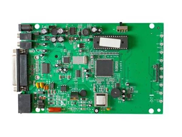
Main Board
The main control board receives signals from the speed control board and the display board to drive the brushless DC motor to run. Includes the following interfaces:
AC220—Connect to single-phase 220V power supply;
MOTO—Connect the main phase wire of the brushless DC motor;
DISPLAY—Connect display board;
HALL—Connect the Hall wire of the brushless DC motor;
SPEED—Connect the speed control board.
Speed Control Board
The speed control board outputs analog signals to the main control board according to the position of the start switch, so as to control the start, speed regulation, brake, etc. of the motor. Connect with the main board.
 Ningbo Etg Tech Ltd
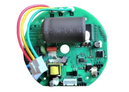 Ningbo Etg Tech Ltd
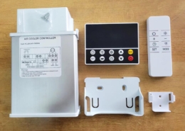 Ningbo Etg Tech Ltd
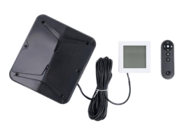 Ningbo Etg Tech Ltd
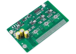 Ningbo Etg Tech Ltd
 Ningbo Etg Tech Ltd
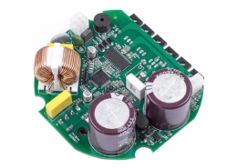 Ningbo Etg Tech Ltd
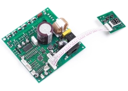 Ningbo Etg Tech Ltd
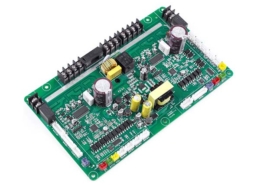 Ningbo Etg Tech Ltd

 Ningbo Etg Tech Ltd
 Ningbo Etg Tech Ltd